Introduction
I’ve been side-tracked for a while doing personal articles, so I thought it would be a good time to get back to some technical explanations. Seeing that I work for Cisco now, I thought it would be a good time to cover some Cisco technology. My focus here has been on programmability and automation. Some of this work has involved using tools like Puppet and Ansible to configure switches, as well as Python and NETCONF. I also recently had a chance to present BRKNMS-2002 at Cisco Live in Las Vegas, on LAN management with Data Center Network Manager 10. It was my first Cisco Live breakout, and of course I had a few problems, from projector issues to live demo failures. Ah well. But for those of you who don’t have access to the CL library, or the time to watch the breakout, I thought I’d cover an important DCNM concept for you here on my blog.
Data Center Network Manager 10
DCNM 10 represents a significant overhaul of the previous version. If you’re not familiar with the product, it has a number of network management features, like configuration backup, software upgrades, and performance management. Version 10 has improved the UI and added a number of new features.
This will be a two-part post covering overlay provisioning. This feature is actually not new, but we did add a new form of overlay provisioning called Top Down. Overlay provisioning is very cool, but I must admit I found some of the concepts a little confusing. In this first post I will cover the concept behind overlay provisioning, and in the second post I will show you examples from a working configuration.
What is overlay provisioning? Imagine you are managing a large, multi-tenant data center. Why would you have such a data center? Well, you could be a service provider hosting multiple tenants (i.e., companies) on the same switch fabric. You need to provide them service while keeping their traffic separate. These days many enterprises build their networks like service providers as well. You might be a large enterprise that needs to keep your manufacturing network separate from your regular employee network.
Let’s also assume you are running a VXLAN/EVPN fabric. Now this is a subject unto itself, and I don’t intend to cover it in detail here. (Several of my colleagues did that and the book is here.) With DCNM and its Power-on Auto-Provision (PoAP) feature, you can actually provision VXLAN/EVPN quite easily without worrying too much about the details. Why would you run a VXLAN fabric? A lot of reasons, really, but one of the biggest ones is that it allows you to have more than the 4000-or-so VLANs a “regular” VLAN-based architecture would permit.
As you may know, VXLAN is essentially a tunneling technology, and tunnels need a way in and out. In the VXLAN world, this entry/exit (or encap/decap) is called a VXLAN Tunnel End Point, or VTEP. Your VTEP could be a physical switch, but it also might be a virtual switch running on a hypervisor. For example, you might have a Nexus 1000v running on VMware.
In such a deployment, what configuration is needed when a “workload” becomes active on a switch? (A workload might be a physical server or a VM.) Well, the switch to which the workload is attached might need:
- A VRF (Remember, we are talking multi-tenancy here!)
- A VLAN
- An SVI (that is, a layer 3 interface for the VLAN)
- A myriad of other stuff
Let’s say we are bringing up a physical server, which is attached to a VTEP. The VTEP needs to be configured with the Blue VRF, VLAN 100, and an ip address of 100.100.100.100 in order to support that server. (Remember that in VXLAN/EVPN, the directly-attached switch is generally the default gateway for servers.) You could configure this manually. This would probably require the server team to file a request or open a ticket with the network team, and then the typing of some CLI. For a small network, this may be all you need to do. But remember, you are managing a large, multi-tenant network with many devices. You don’t want to do everything manually.
Enter DCNM
DCNM 10 has two modes of overlay provisioning: Top-Down and Bottom-Up. The latter is also known as Auto-Configuration. As I mentioned, top-down is a new feature, but auto-configuration has been around for a while. In either case, the idea is that you are sending configuration to the device from DCNM instead of doing it by hand. In order to understand the difference between Top-Down and Bottom-Up provisioning, we need to understand what we mean by “top” and “bottom”. In a typical diagram, the DCNM will sit at the top, and the switches at the bottom. Therefore, Top-Down provisioning means DCNM initiates the configuration of the switch. Bottom-up provisioning means the switch actually initiates its own configuration.
Auto-Configuration
Let’s look at Bottom-Up mode, also known as Auto-Configuration, in more detail.
Auto-configuration automatically provisions the network in response to workloads. The basic premise is that when a workload (VM or physical host) becomes active, the switch becomes aware of it and then pulls down the relevant configuration from DCNM. The switch can become aware of a workload through one of several triggers. I’m not going to discuss all of them here, but I will use two for demonstration:
- Dot1Q triggering. The switch sees a packet on a host-facing trunk link which is tagged with a VLAN, and then requests the appropriate configuration. The host-facing trunk is most likely connected to a physical host running a hypervisor like ESX. Thus, it hosts multiple virtual machines in different VLANs/subnets, and possibly even tenants.
- VMTracker triggering. The switch is notified of a a new VMware VM by Vcenter, and then requests and applies the appropriate configuration. Unlike dot1q, this is not a passive, data-driven form of triggering, but is an active connection between the switch and vCenter. (Note well: Between the switch and vCenter, not DCNM and vCenter.)
Note that the configuration request is very switch-centric. It is the switch that learns of an active workload, and it is the switch that requests configuration from DCNM.
DCNM Terminology
I’d like to review some DCNM-specific terminology before moving on. Because DCNM is multi-tenant and multi-fabric, there is a bit of jargon you need to understand in order to follow along.
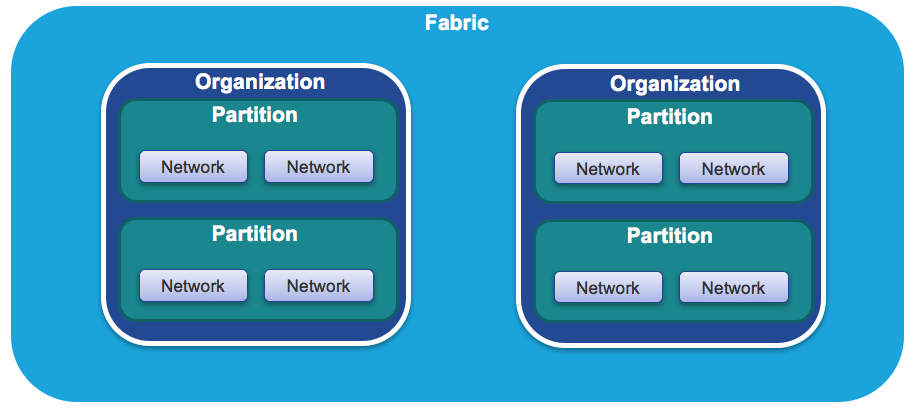
- Organization: This is simply a tenant. As mentioned before, it could be a company hosted in a multi-tenant data center, or it could be an entity within an enterprise.
- Partition: This is DCNM jargon for a VRF. Each organization can have multiple VRFs.
- Network: This is, well, a network. Each VRF can have multiple networks, and you can overlap IP address ranges.
All of these are rolled up into a fabric, which is just a collection of switches running a protocol like VXLAN. And yes, DCNM can have more than one fabric.
A walk-through
How does this all come together? First, you define the VRF and network parameters in DCNM. These define the VRF name, the VLAN ID, and the subnet and anycast gateway. Then, when a workload becomes active, the switch queries DCNM for this information. Let’s look at a specific example, assuming you’ve configured DCNM already with the relevant parameters.
Note: We’ll look at how to do this in the next article.
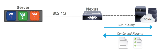
Imagine we have a server which is running a hypervisor of some sort, such as ESXi. This server has an 802.1q link up to its Nexus switch. This is a typical configuration for a virtual machine host, because the different VMs are usually in different VLANs/subnets. In VMware, VMs are assigned to subnets by using port groups, but the details aren’t important. In our setup, there are two existing VMs, and the Nexus is being managed by DCNM.
Now imagine a third VM becomes active, and that it is on VLAN 77, a VLAN which is not configured on our Nexus. Because we are doing full-blown VXLAN with anycast gateway, the switch needs to have the VLAN provisioned along with a VRF and SVI.
The VM begins sending traffic, blissfully unaware that it’s switch isn’t ready for it. However, the switch sees this dot1q traffic, and recognizing it needs configuration, it sends a request to DCNM. DCNM then replies with the configuration needed, in template form, plus the parameters (or variables) needed to fill out the template. The switch merges them together and applies the configuration, enabling access for the VM. Where does DCNM get this information? Well, it gets the configuration information from a template, and the parameters from the screen you filled out when defining the network. It’s also possible for a third party orchestrator to pass the requisite data to DCNM, but we won’t go that far in this article.
Top-Down
The top down approach is manual. It is not auto-configuration. You fill out the same template in DCNM, but to push the configuration you have to push a button in DCNM. This is still easier than typing a bunch of CLI, but not as cool as the network configuring itself!
Push-Pull
I didn’t want to cover this, except that it is very confusing and you may come across it somewhere. Push-pull is an auto-configuration mode in which you press a button on DCNM and the switch pulls its configuration down. You may be wondering how this is different from Top-Down. Well, in Top-Down mode, DCNM pushes the configuration to the switch. In push-pull mode, DCNM tells the switch to pull down the configuration. In other words, in push-pull mode, the switch is asking for its configuration just like it would with a dot1q or VMTracker trigger. The difference is that the trigger is you pushing a button, but at the end of the day, the switch is still asking for config. In Top-Down the switch doesn’t ask for anything; DCNM just sends it. Thus the name push-pull. DCNM pushes the switch to pull its configuration. Try not to think about it too long.
Conclusion
We’ve covered the basic concepts behind auto-provisioning in this post. If they seem confusing, they should clear up in the next post, where I demonstrate an actual auto-provisioning event and show you how easy it makes VXLAN configuration.


4.5
5