In this post, we’ll be looking at IS-IS inter-area concepts, and hopefully clearing up some of the confusion ISIS areas create in the minds of engineers who are used to OSPF. ISIS handles areas quite differently from OSPF, and if you think about ISIS areas in OSPF terms you are likely to be confused by some of this behavior. The good news is that if you configure area numbers and enable ISIS, it should just work, but if you want to do anything more complex you will need a deeper understanding of how ISIS areas work. I’ll assume you know the basics of ISIS, for example that it is not an IP native protocol, and just focus on the areas for now. My intention here is not to go into all of the details of ISIS inter-area operation, but to help you sort out the basics in your mind so you can dive deeper in your studies. All output will be from Juniper routers, but should be self-explanatory enough for those of you using a different platform.
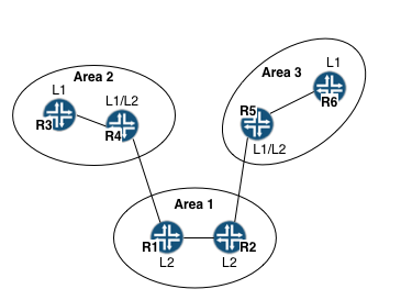
When studying ISIS, you will typically come across an area diagram that looks like this:

And as an OSPF engineer, you will typically think the following:
Great! The middle area (area 1) with the two L2 routers is like area 0. The L1/L2 routers are the ABRs, which appear only on area boundaries. The L1 routers are like OSPF internal routers that have no connections to external areas. And the L2 routers are just ABRs which sit in the backbone.
Note: An area X is actually area 49.000X. So the area labeled “1” is area 49.0001.
The problem is that if you set this up in the lab, this isn’t quite the behavior you will see. Let’s take a further look by doing just that.
The first thing we expect to see is a simple L1 adjacency between R3 and R4. After all, they are both in the same area, and R3 has no connections to any other area. But when we look at the output on R3, we see something odd:
root@r3> show isis adjacency

Interface             System         L State        Hold (secs) SNPA

ge-0/0/1.0            r4             1  Up                   20  56:68:29:7a:9c:ed

ge-0/0/1.0            r4             2  Up                   25  56:68:29:7a:9c:ed
R3 has two adjacencies to R4, one level 1 adjacency and one level 2 adjacency. Something doesn’t seem right here.
Note: On a Cisco router you will not see two separate lines in your output, but a single line that shows an “L1L2” adjacency. This is the same thing as the two separate adjacencies shown by Junos.
On the other end of this connection, R4 of course has the two adjacencies to R3, but it has only one L2 connection to R1, as we’d expect, since R1 is in a different area:
root@r4> show isis adjacency

Interface             System         L State        Hold (secs) SNPA

ge-0/0/1.0            r3             1  Up                    6  56:68:29:7a:be:6e

ge-0/0/1.0            r3             2  Up                    7  56:68:29:7a:be:6e

ge-0/0/2.0            r1             2  Up                    7  56:68:29:7a:a0:4f
Our diagram shows R1 and R2 as level 2 routers only. However, when we look at their adjacencies, once again we see something confusing:
root@r1> show isis adjacency

Interface             System         L State        Hold (secs) SNPA

ge-0/0/1.0            r2             1  Up                    8  56:68:29:7a:b0:37

ge-0/0/1.0            r2             2  Up                    7  56:68:29:7a:b0:37

ge-0/0/2.0            r4             2  Up                   22  56:68:29:7a:9c:ff
Once again, R1 has a dual L1/L2 adjacency to R2, even though they are both shown as L2 on our diagram. I won’t repeat the outputs for R5 and R6, because they look exactly the same as in area 2.
While this behavior may seem strange, ISIS, by default, will form both L1 and L2 adjacencies to a neighbor when that neighbor is in the same area. If the neighbor is not in the same area, it cannot and will not form an L1 adjacency, but only an L2 adjacency. We can control this by specifying routers in the same area form only one or the other type, but the default is to form both.
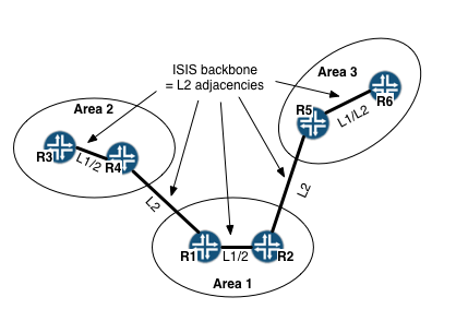
ISIS backbone = L2 adjacencies
It is important to keep in mind a point made by Jeff Doyle in his classic Routing TCP/IP, Volume I. We shouldn’t think of the backbone area in ISIS like the backbone area in OSPF. The backbone in ISIS is not so much an area, but is really just the collection of L2 adjacencies in the network. Since in our network we have a path of L2 adjacencies stretching from R3 all the way to R6, really the backbone runs across our whole network. This means that our backbone in ISIS includes routers, such as R6, that are entirely within a single ISIS area, and have no connections to any other areas.

If I go to R6 and examine the route to the network between R3 and R4, I can see that it is known as a level 2 route:
root@r6> show route 10.1.34/24 detail

inet.0: 9 destinations, 9 routes (9 active, 0 holddown, 0 hidden)

10.1.34.0/24 (1 entry, 1 announced)

*IS-IS  Preference: 18

Level: 2

<…>
Cisco people: yes, in Junos you can examine a prefix without listing all four octets!
We can force the routers into the configuration shown on our diagram by disabling the appropriate adjacency levels. In Junos this is done as follows:
root@r2# set protocols isis interface ge-0/0/1.0 level 1 disable

[edit]

root@r2# run show isis adjacency

Interface             System         L State        Hold (secs) SNPA

ge-0/0/1.0            r1             1  Down                  0  56:68:29:7a:a5:d1

ge-0/0/1.0            r1             2  Up                   23  56:68:29:7a:a5:d1
…and here we can see the same being done for an L1 router with a similar effect…
root@r3# set protocols isis interface ge-0/0/1.0 level 2 disable


[edit]

root@r3# run show isis adjacency

Interface             System         L State        Hold (secs) SNPA

ge-0/0/1.0            r4             1  Up                   21  56:68:29:7a:9c:ed

ge-0/0/1.0            r4             2  Down                  0  56:68:29:7a:9c:ed
Note: In Junos routers, you can use the run command from configuration mode to run show commands. Using show in configuration mode shows parts of the configuration only. This is similar to the “do” command in IOS.
It is important to note here that in ISIS, it is possible for routers in the same area to have either and L1 or an L2 adjacency, or both. Routers in different areas can have only an L2 adjacency.
Having set all routers manually to their proper role, we now see that the route on R6 to the R3-R4 network has disappeared. In fact, the only route we have, in addition to R5’s directly attached route, is a default route:
root@r6> show route 10.1.34/24 detail


root@r6> show route protocol isis


inet.0: 6 destinations, 7 routes (6 active, 0 holddown, 0 hidden)

+ = Active Route, - = Last Active, * = Both


0.0.0.0/0           [IS-IS/15] 00:00:10, metric 10

> to 10.1.56.5 via ge-0/0/1.0

10.1.25.0/24       *[IS-IS/15] 01:20:08, metric 20

> to 10.1.56.5 via ge-0/0/1.0
In ISIS, all L1 areas function similarly to an OSPF totally stubby area, and receive only a default route to networks outside of the immediate area. R5 does inject his local routes into the L1 area, but none of the L2 routes he knows.
Note: An ISIS Level 1 area is really closer to an OSPF totally stubby NSSA since it can accept external routes, but we won’t be looking at that in this example.
Breaking the Back(bone)
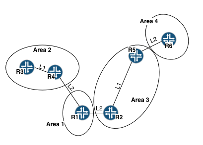
Let’s look at a further example of the ISIS backbone concept. In this example I’ve reconfigured the areas so as to split the backbone (the collection of L2 adjacencies) into two, with an L1 adjacency in between:
In this case, we have broken connectivity across the topology. The L2 backbone is severed by a level 1 adjacency. R5, although having a L1 adjacency, sees itself as an L1/L2 router since he also has a L2 adjacency:
root@r5# run show isis adjacency


Interface             System         L State        Hold (secs) SNPA

ge-0/0/1.0            r6             2  Up                    8  56:68:29:7a:af:1f

ge-0/0/2.0            r2             1  Up                    8  56:68:29:7a:9f:c3
Therefore, despite the L1 adjacency, R5 does not act as if it is in a “totally stubby” area and install a default route. Connectivity is broken and the backbone is severed.
Summary
I hope this article helps to clear up some of the confusion with ISIS areas. In closing, some key points to remember:
- An ISIS router is in one area only, and cannot be in multiple areas like OSPF.
- An L1 adjacency is formed only with routers in the same area.
- An L2 adjacency is formed with routers in the same area or a different area.
- An ISIS router will form L1 and L2 adjacencies by default with a router in the same area.
- Either L1 or L2 adjacencies can be disabled for a router in the same area.
- The collection of L2 adjacencies is considered the ISIS backbone, not any particular area.
- Therefore, the ISIS backbone can span multiple areas.
- An ISIS router with only an L1 adjacency will receive only its local L1 routes and a default route, but will have no routes outside the area.
I was so confused with few of the IS-IS terms such as L1/L2 routers. However, now I got the clear idea. Thanks for sharing the nice article.
Thanks for the comment! An old post but glad it helped.
4
5
Thanks for this, just what was looking for
Happy to know my old posts are still proving valuable!
Hey Jeff, thanks for this. I think learning IS-IS without having first learned OSPF would’ve been easier. But then that probably would’ve made learning OSPF harder, lol.
4.5
4.5